Pneumatic Flange Butterfly Valve

A robust and reliable butterfly valve featuring integral flanges for direct bolting to pipeline flanges, powered by a pneumatic actuator for automated on/off or modulating flow control in demanding industrial applications.

View Technical Specs
DIN Resilient Seated NRS Gate Valve

Product Overview

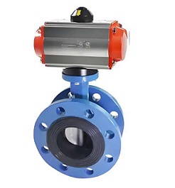
The Pneumatic Flange Butterfly Valve is designed for applications requiring a secure, leak-tight connection and high structural integrity. Unlike wafer or lug valves, it features its own integral flanges that are bolted directly to the mating flanges of the pipeline. This design provides a robust and rigid connection, making it ideal for high-pressure, high-temperature, or vacuum services where joint integrity is paramount.

Equipped with a powerful pneumatic actuator, this valve offers fast and reliable automated operation. The actuator can be controlled by a solenoid valve for simple on/off functions or paired with a positioner for precise modulating control using 4-20mA signals, allowing for accurate flow rate adjustment in process control systems.

Constructed from heavy-duty materials such as ductile iron, carbon steel, or stainless steel, and featuring resilient seats (EPDM, NBR, PTFE) or metal seats (Stellite), the Pneumatic Flange Butterfly Valve delivers exceptional performance and longevity in a wide range of media, including water, steam, oil, gas, chemicals, and slurries. Its versatility and durability make it a preferred choice for industries such as power generation, oil & gas, chemical processing, water & wastewater, and pulp & paper.

Key Features & Benefits

Pneumatic Actuation

Provides fast, efficient, and reliable automated operation using compressed air, suitable for remote control and integration into PLC/DCS systems.

Integral Flange Design

Features its own flanges for direct bolting to pipeline flanges, ensuring a secure, leak-tight connection and excellent structural rigidity for high-pressure and vacuum applications.

Modulating Control Option

Can be equipped with a positioner for proportional flow control using 4-20mA signals, enabling precise flow regulation in automated process systems.

Resilient or Metal Seating

Offers a choice of resilient seats (EPDM, NBR, PTFE) for excellent sealing at moderate temperatures or metal seats (Stellite) for high-temperature and abrasive media applications.

Heavy-Duty Construction

Built with robust materials (ductile iron, carbon steel, stainless steel) to withstand harsh operating conditions, ensuring long service life and minimal maintenance.

ISO 5752 & API 609 Compliance

Designed and manufactured to meet international standards, ensuring compatibility, reliability, and interchangeability in global industrial applications.

Technical Specifications

Basic Parameters

Parameter Specification Range
Nominal Diameter (DN/NPS) DN50 ~ DN2400 (2" ~ 96")
Nominal Pressure (PN/Class) PN10, PN16, PN25, PN40
Class 150, Class 300, Class 600
Operating Temperature -40°F ~ 1112°F (-40°C ~ 600°C) (Depends on seat material)
Applicable Media Water, Steam, Oil, Gas, Chemicals, Slurries, Abrasive Media
Sealing Class ISO 5208 Class IV, V, or VI (Metal seat)

Material Specifications

Component Material Options Standards/Features
Valve Body Ductile Iron, Carbon Steel, Stainless Steel EN-GJS-400-15, ASTM A216 WCB, ASTM A351 CF8/CF8M
Disc Ductile Iron, Stainless Steel, Ni-Resist, Alloy Steel EN-GJS-400-15, AISI 304/316, Ni-Resist D2, ASTM A182 F304/F316
Seat EPDM, NBR, PTFE, PFA, Metal (Stellite) Resilient: Corrosion/Temperature Resistant
Metal: High Temp, Abrasion Resistant
Shaft Stainless Steel, Alloy Steel AISI 304/316, ASTM A182 F6a
Actuator Pneumatic (Double-Acting or Spring-Return) 5-10 bar (70-145 psi) Air Supply, Positioner (4-20mA) Option

Standards & Compliance

  • Design Standards: ISO 5752, API 609
  • Flange Standards: ISO 7005-1, ANSI B16.5 Class 150/300/600, DIN
  • Testing Standards: ISO 5208, API 598
  • Certifications: CE, ISO 9001, API 609

Working Principle

The Pneumatic Flange Butterfly Valve operates using a rotating disc controlled by a pneumatic actuator, with its integral flanges providing a secure connection to the pipeline:

  1. Pneumatic Actuation: The pneumatic actuator receives compressed air signals from a control system (e.g., solenoid valve or positioner) and rotates the valve shaft to open or close the disc.
  2. Opening Process: Rotating the disc to a parallel position with the flow direction allows media to pass through the valve with minimal pressure drop.
  3. Closing Process: Rotating the disc to a perpendicular position blocks the flow path. For resilient seated valves, the disc compresses the seat for a tight seal. For metal seated valves, the metal-to-metal contact provides a high-integrity seal suitable for high temperatures and pressures.
  4. Modulating Control: When equipped with a positioner, the actuator adjusts the disc position based on an input signal (e.g., 4-20mA) to maintain a desired flow rate, enabling precise process control.
  5. Flange Connection Benefit: The integral flanges are bolted directly to the pipeline flanges, creating a rigid and leak-tight joint. This design is particularly advantageous for high-pressure, high-temperature, or vacuum applications where joint integrity is critical.

Application Areas

Power Generation

Boiler feedwater, cooling water, and flue gas desulfurization systems, requiring reliable operation at high pressures and temperatures.

Oil & Gas

Upstream, midstream, and downstream applications, including wellhead control, pipeline transportation, and refinery processes, where robust sealing and high-pressure ratings are essential.

Chemical Processing

Handling a wide range of corrosive and hazardous chemicals, where the flange connection ensures leak-tight operation and compatibility with various piping systems.

Water & Wastewater

Municipal water supply, wastewater treatment, and industrial water systems, providing reliable flow control and easy integration into automated processes.

General Industry

Pulp & paper, food & beverage, mining, and HVAC systems, where the flange design offers easy installation, maintenance, and compatibility with standard piping flanges.

Vacuum Systems

Ideal for vacuum applications where the flange connection provides the necessary structural integrity and leak-tight performance to maintain system vacuum.

Installation & Maintenance

Installation Guidelines

  • Inspect the valve and actuator for damage before installation. Ensure the valve is in the closed position.
  • Clean the pipeline flanges and ensure they are flat, parallel, and free of debris. Check that the flange face finish meets the required standard (e.g., RF, RTJ).
  • Position the valve between the pipeline flanges, ensuring proper alignment of the flange bolt holes. Use appropriate gaskets (e.g., spiral wound, non-asbestos) between the valve and pipeline flanges.
  • Insert the flange bolts through the valve and pipeline flanges. Tighten the bolts evenly in a crisscross pattern to the recommended torque specification to ensure a uniform seal and prevent flange warping.
  • Connect the actuator to the air supply and control system according to the manufacturer's instructions. Ensure proper air pressure and signal wiring.
  • Conduct hydrostatic testing (1.5×PN) and leakage testing after installation to verify performance and ensure a leak-tight seal.

Maintenance Recommendations

  • Regularly inspect the valve for leaks, corrosion, or damage. Check the flange bolts for tightness and retorque if necessary.
  • Clean the valve interior periodically to remove any buildup or debris that may affect operation. For resilient seated valves, inspect the seat for signs of wear or damage and replace if necessary.
  • Check the actuator air supply and connections for leaks or blockages. Replace any faulty components (e.g., solenoid valve, positioner) as needed.
  • Lubricate the actuator bearings and gearbox (if equipped) annually or as per manufacturer recommendations to ensure smooth operation.
  • For maintenance or replacement, the entire valve must be removed from the pipeline by unbolting the flange connections. This may require disconnecting adjacent piping or using spool pieces for easier removal.
  • Follow the manufacturer's recommended maintenance schedule and procedures to ensure optimal performance and extend the service life of the valve.

Frequently Asked Questions (FAQ)

Q: What is the difference between a flange butterfly valve and wafer/lug butterfly valves?

A: A flange butterfly valve has its own integral flanges and is bolted directly to pipeline flanges, providing a robust and leak-tight connection ideal for high-pressure/temperature or vacuum applications. Wafer valves are clamped between flanges without their own bolts, and lug valves have lugs for independent mounting and easy removal, but both use the pipeline bolts for installation.

Q: Can a Pneumatic Flange Butterfly Valve be used for high-temperature applications?

A: Yes, depending on the seat material. Resilient seats (EPDM, NBR) are suitable for moderate temperatures (up to ~392°F / 200°C), while metal seats (Stellite) can handle high temperatures up to 1112°F (600°C) or more. The flange design provides the necessary structural integrity for high-temperature service.

Q: What is the maximum pressure rating for a Pneumatic Flange Butterfly Valve?

A: The maximum pressure rating depends on the valve size, material, and design. Flange butterfly valves are typically available in PN10 to PN40 (1.0 MPa to 4.0 MPa) or Class 150 to Class 600 (2.0 MPa to 10.0 MPa). Consult the technical specifications for exact pressure ratings for your specific application.

Q: Is the Pneumatic Flange Butterfly Valve suitable for slurry applications?

A: Yes, it can be used for slurry applications with appropriate material selection (e.g., Ni-Resist disc, hard-faced seats) and design considerations. The flange connection ensures a secure joint that can withstand the abrasive nature of slurries. Consult with our engineering team to determine the best configuration for your specific slurry application.

Q: Can the Pneumatic Flange Butterfly Valve be used for modulating control?

A: Yes, when equipped with a pneumatic positioner that accepts 4-20mA control signals, the valve can be used for modulating control to adjust flow rates precisely. However, for highly precise flow control applications, a control valve with a characterized trim may be more suitable.

Need Custom Solutions?

Our engineering team can customize Pneumatic Flange Butterfly Valves to meet your specific pressure, temperature, and media requirements. Contact us today for a personalized quote.

Contact Our Technical Team